Mini Implants Guided Surgery

Dr. IOANA DATCU
Country: Italy
Gallery
Patient's Data:
- Age: 90
- Sex: Female
- Smoker: No
- Pathologies: None
- Hygenic state: Fair
- Alergies: None
The use of Cone Beam CT scanning combined with improved software technology has led to an increase in digital planning and guided surgery in conventional implant dentistry. This case demonstrates that these tools can also be used in combination with Mini Dental Implants (MDI).
Dental implants have long been used to stabilise overdentures as well as help maintain bone levels, improve function and phonetics in an edentulous patient. Conventional implants have been traditionally used, but with implant widths varying between 3.0mm – 7mm wide these have not always been suitable for patients with restricted bone volume, unless bone grafting procedures are undertaken.
MDIs can be placed in situations with limited space and bone volume, due to their reduced diameters, ranging from 1.8mm – 2.4mm. As a one-piece implant, MDIs with an O-Ball head can be used to stabilise an overdenture, and often in mandibular cases can be immediately loaded. A minimally invasive surgical procedure, often with a flapless approach, frequently results in reduced post-operative pain for the patient as well as the associated benefits of reducing surgical time.
Case Study
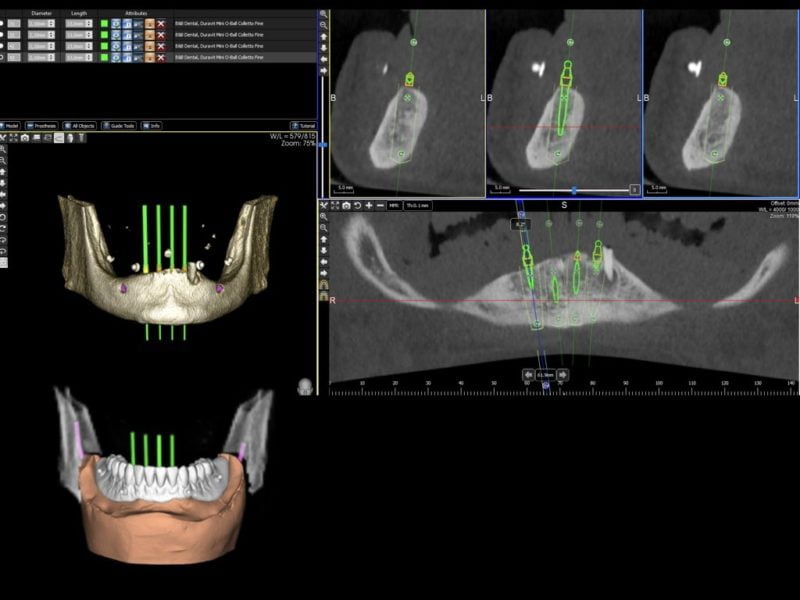
A 90-year-old female patient presented with an edentulous mandible (the lower left canine root was still present) in need of denture stabilisation. A Cone Beam CT scan was undertaken to establish bone volume and gain an accurate 3D image of the mandibular architecture. 3 Diemme (Cantù, Italy) planning software was utilised to plan the case and allowed for virtual implant placement to produce optimal positioning of the implants. In line with MDI protocol, these implants were planned to be placed inter-foraminally.
Surgical Phase
In this case, it was determined that four MDIs (MDI Implantology, Bologna, Italy) with a diameter of 2.1mm and a length of 13mm would be the most suitable implants to retain and stabilise the existing denture. Figures 1 and 2 show the virtual implant placement and a digital model superimposed on the tomograph showing the denture in place.
A drilling template was designed and verified via the software and produced by dental laboratory incorporating four guide sleeves with a diameter of 2.65mm to guide the drills in creating the osteotomies. Two further lateral guide sleeve were incorporated into the labial aspect of the guide to enable lateral fixation of the guide should it be required during surgery (figure 3).
The surgical protocol for the MDI guided surgery system is made of two sets of three drills each; long and short drills in the diameters of 1.1mm, 1.3mm and 2.0mm. The length of drill selected is dependant on the length of implant to be used. This allows the user to have guidance and follow the standard MDI protocol of under preparation of the site with a drill diameter that is less than the diameter of the implant as well as creating an osteotomy that is one third the total length of the implant. In the case of hard bone being encountered, the user has the option of drilling deeper or wider through the same sleeve guidance.
In following the standard protocols for MDI placement, this type of guided surgery differs from that using conventional implants in that it provides directional guidance but is not able to provide full depth and placement guidance for the implant. Guided surgery with conventional implants is routinely carried out with definitive depth stops on the drills and width sleeves in the guide. The wider diameter of conventional implants precludes the need to underprepare the osteotomy.
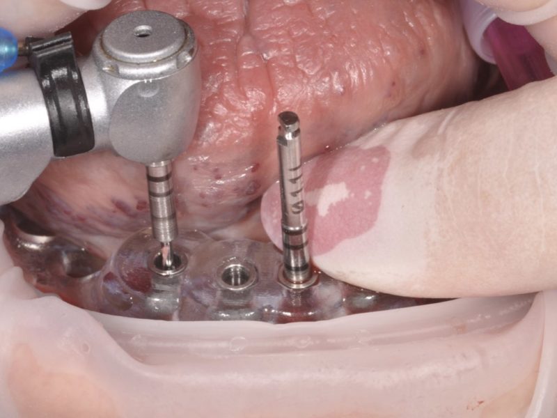
The surgical procedure commenced with the extraction of the canine root. The guide was then placed, and the osteotomies were created utilising first an initial 1.1mm diameter drill and then a 1.3mm drill at a recommended drill speed of 1500 rpm. Standard MDI protocol is to drill to a depth of one third the length of the implant. In this particular case the bone was dense, so each osteotomy was drilled to a depth of 10mm (figure 4). In this case, lateral pin fixation was not used to keep the surgical procedure as simple as possible, but once the first site was prepared, the 1.1mm drill was used to provide crestal fixation (figure 5).
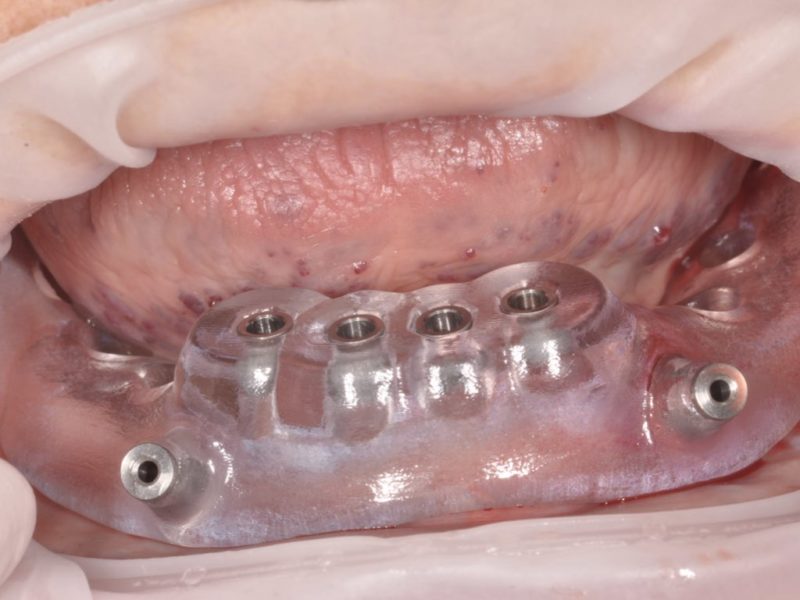
The implants were then placed sequentially. Placement protocol is for an initial insertion using the implant mount cap as the initial driver (figure 6). Throughout all stages of implant placement, great care was taken not to exert too much torque on the implant (i.e. not to exceed 50Ncm). Once the resistance was too great to proceed further with the cap, the butterfly driver was used to insert the implant further, prior to using the torque wrench to finally seat the implant fully down. Once all implants were placed and finally seated peri-apical radiographs were taken to confirm correct seating (figures 7-10).
Prosthetic Phase
In this case, the patient’s existing denture was adapted to be secured by the implants. The position of the implant ball heads was captured relative to the denture and the positions marked on the denture. The denture base was relieved to accommodate the ball heads of the implants as well as the housing units so that the denture sits passively over the housing units. Once adapted the denture was fully cleaned of all acrylic residue (figures 11-13).
Rubber dam was placed over the implant heads to protect the soft tissue and acrylic shims approximately 1.5mm in length were placed around the necks of the implant, but below the O-ball head, to block out any undercuts. The housing units were placed over the O-ball heads and were checked to ensure full seating. Cold cure acrylic was applied to the hollowed trough in the denture base and the denture was set over the housing units in the patient’s mouth. The patient was asked to bite together with normal force for 8 minutes to allow the acrylic to set. The denture was then finally trimmed and polished for the final fit (figure 14).
Discussion
Digital planning and workflow is rapidly becoming a standard protocol in implant dentistry and these concepts can be extended to Mini Dental Implants that are used to stabilise overdentures. MDIs can offer advantages over conventional implants in this role, especially where bone volume is deficient and where bone augmentation procedures may not be the optimal solution due to clinical or financial reasons. MDI offer a minimally invasive, safe and cost-effective solution for selected patients.
The use of Cone Beam Computerised Tomography (CBCT) allows for virtual implant placement in planning software which allows a surgical guide to be produced allowing proper placement, spacing and parallel alignment of the implants. The guide also allows for a flapless procedure to be undertaken where there is sufficient bone width. This reduces patient morbidity and healing time as well as the benefit of reduced surgical time.